
Home > Industry Information > An In-Depth Look At The I2C Interface
This document provides a comprehensive technical introduction to the I2C (Inter-Integrated Circuit) serial communication protocol. It explains the protocol's origins, its simple two-wire operational principle involving START/STOP conditions and addressing, and details its key characteristics such as multi-master support and clock stretching. The text also objectively analyzes the strengths and limitations of I2C, illustrates its widespread applications in modern electronics, and concludes with a concise comparison to the SPI interface to highlight its unique design philosophy and trade-offs.
I2C, short for "Inter-Integrated Circuit", was invented by Philips Semiconductors in the 1980s. Designed as a communication bridge between integrated circuits, its original purpose was to connect numerous low-speed peripheral devices, such as sensors and memory chips, on a single Printed Circuit Board (PCB) using the most minimal wiring. After decades of development, I2C has become one of the most widely used serial communication protocols in embedded systems, thanks to its elegant and straightforward design.
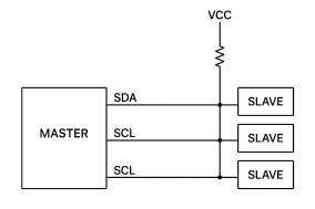
The physical layer of I2C is remarkably simple, consisting of just two wires: the Serial Data Line (SDA) for data transmission and the Serial Clock Line (SCL) for the synchronous clock. Both lines use an open-drain/open-collector output design and must be connected to a positive supply voltage via pull-up resistors. This "wired-AND" logic structure is fundamental to allowing multiple devices to share the bus and for collision arbitration.
In terms of communication flow, all interactions are initiated and controlled by the Master device. A complete I2C transaction unfolds like a classic four-act play:
START Condition: The Master initiates communication by pulling the SDA line from HIGH to LOW while the SCL line is HIGH.
Addressing: The Master sends a 7-bit or 10-bit slave device address, followed by a single Read/Write bit. All slave devices on the bus listen to this address. Only the slave whose address matches will acknowledge by pulling the SDA line LOW (sending an ACK bit).
Data Transfer: After the address is acknowledged, the Master and Slave begin transferring data byte by byte. After every 8 bits of data sent, the receiver must send an ACK bit. Data on the SDA line must remain stable when SCL is HIGH and can only change when SCL is LOW.
STOP Condition: The Master terminates the communication by pulling the SDA line from LOW to HIGH while SCL is HIGH, releasing control of the bus.

The beauty of I2C lies in its complete and flexible communication management mechanisms, built upon minimal hardware requirements:
Feature/Mechanism | Description |
Multi-Master, Multi-Slave | A single bus can connect multiple master and multiple slave devices. If multiple masters start transmission simultaneously, the bus uses an arbitration mechanism to automatically decide a winner, ensuring only one master proceeds without data corruption. This makes it a true multi-master bus. |
Software Addressing | Each slave device has a unique, often software-configurable address. The host calls a device by broadcasting its address, eliminating the need for extra chip-select lines and greatly simplifying system connections. |
Speed Grades | Supports multiple speed modes for different devices: Standard-mode (100 kbps), Fast-mode (400 kbps), High-speed mode (3.4 Mbps), etc. High-speed and low-speed devices can coexist on the same bus. |
Clock Synchronization & Stretching | Allows devices with different processing speeds to work together. If a slave is busy, it can stretch the clock by holding the SCL line LOW, forcing the master into a wait state. This enables reliable communication with slower peripherals. |
The I2C design offers significant advantages in specific scenarios but also comes with inherent limitations:
Key Strengths:
·Resource-Efficient: Requires only two wires, greatly conserving valuable MCU pins and PCB routing space.
·Easy to Expand: Adding a new device simply involves connecting it in parallel to the bus and assigning a unique address, making system design highly modular.
·Supports Multi-Master: Suitable for complex systems requiring multiple controllers.
Key Challenges:
·Short Communication Distance: As it uses level-signaling, it's susceptible to interference and signal attenuation. It's typically suited for board-level or short-distance communication (usually under 1 meter).
·Relatively Low Speed: Compared to parallel or high-speed serial buses like SPI, I2C's data rate is limited and not ideal for applications requiring extremely high throughput.
·Software Overhead & Level Compatibility: The master device's CPU must manage the full protocol via software or a hardware controller. When devices on the bus operate at different voltages, additional level-shifting circuits are needed for reliable communication.
Due to its simplicity, flexibility, and space-saving nature, I2C is ubiquitous in the following areas:
Sensor Networks: Connecting temperature sensors, humidity sensors, barometers, accelerometers, gyroscopes, etc. It's a critical link in smartphones and IoT devices.
Display & Driver Control: Controlling small OLED/LCD displays, LED driver chips, and GPIO port expander chips.
System Management: Accessing EEPROM memory to store configuration parameters or communicating with smart battery management chips and power management ICs. A subset of I2C, the System Management Bus (SMBus), is specialized for this domain.
Consumer Electronics & Industrial Control: From tuner control in TVs and set-top boxes to low-speed data exchange between modules in industrial PLC systems.

In the embedded world, the Serial Peripheral Interface (SPI) is I2C's primary competitor. The table below highlights their core differences:
Feature | I2C Interface | SPI Interface |
Number of Wires | 2 wires (SDA, SCL) | Minimum 3-4 wires (SCLK, MOSI, MISO, plus a separate Slave Select (SS) per slave) |
Communication Mode | Half-duplex (one direction at a time) | Full-duplex (can send and receive simultaneously) |
Topology | Multi-master, multi-slave, bus topology | Single-master, multi-slave, typically star topology (requires chip select lines) |
Addressing | Software addressing (broadcast address) | Hardware addressing (via dedicated chip select lines) |
Maximum Speed | Relatively lower (Fast-mode 400kbps, High-speed mode 3.4Mbps) | Very High (often tens of Mbps or higher) |
Protocol Complexity | More complex protocol (START/STOP/ACK) | Simpler protocol (essentially a clocked shift register) |
Primary Advantage | Pin-efficient, supports multi-master, easy to expand | Very high speed, simple protocol, full-duplex operation |
In conclusion, the I2C interface stands as a masterclass in minimalist and elegant engineering for short-range, board-level communication. Its defining two-wire, multi-master bus architecture has proven exceptionally effective for connecting a plethora of low-to-medium speed peripherals, from sensors to memory chips. While its limitations in speed and distance are clear, its unparalleled efficiency in saving pin count and simplifying hardware design ensures its enduring and indispensable role as a foundational technology in embedded systems and consumer electronics.
Industry Information








