
Home > Industry Information > Exploring The Role Of Camshaft Sensors
This passage provides a comprehensive introduction to the camshaft position sensor, covering its basic concepts, types, application fields with specific vehicle models, common faults and repair methods, as well as a summary. It aims to offer a clear and detailed understanding of this crucial component in automotive engine systems, highlighting its role, characteristics, and practical significance.
2.1 What precisely is position sensor
A position sensor is a device that converts the positional information of an object into electrical signals. It can detect the position or displacement of an object in space and transform this information into electrical signals that are easy to process, transmit, and store. This enables the monitoring and control of the object's position, making it widely used in numerous fields such as industrial automation, robotics, and automotive electronics.
2.2 What is a Camshaft Position Sensor
A camshaft position sensor is an important sensor installed in a car engine. Its main function is to detect the position and rotational speed of the camshaft. By sensing the changes in the camshaft's angle, it provides the camshaft position signal to the Engine Control Unit (ECU). Based on these signals, the ECU can accurately determine the piston position and valve timing of the engine, thereby controlling key parameters such as fuel injection quantity and ignition timing to ensure the engine operates normally and efficiently.
2.3 The importance of Camshaft Position Sensor
The camshaft position sensor plays a vital role in the engine system. Accurate camshaft position information is essential for the ECU to make precise control decisions. Without a properly functioning camshaft position sensor, the engine may experience difficulties in starting, unstable idling, reduced power output, increased fuel consumption, and even failure to run. It directly affects the engine's performance, fuel efficiency, and emissions, making it a critical component for the overall operation of the vehicle.
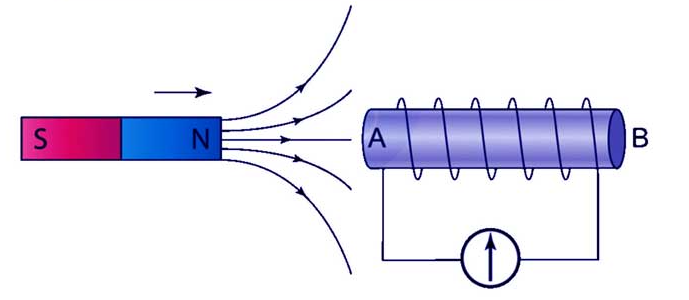
Electromagnetic Induction Type:Composed of a permanent magnet, coil, and iron core. When the signal wheel rotates, it changes the magnetic resistance in the magnetic circuit, generating an induced electromotive force in the coil. The signal strength varies with rotational speed, with higher speeds producing stronger signals. It is suitable for various engine operating conditions.
Hall Effect Type:Based on the Hall effect, it includes a Hall element, permanent magnet, and signal wheel. As the signal wheel rotates, the alternating teeth and slots alter the magnetic field, causing the Hall element to output voltage signals. It features stable output signals and high accuracy, making it widely used in modern automobiles.

Photoelectric Type:Consists of a light-emitting diode, phototransistor, and signal wheel. Light from the diode is either transmitted through the signal wheel's slots or blocked by its teeth, leading the phototransistor to generate switching signals. However, it has high requirements for the cleanliness of the working environment, as it is susceptible to contamination by oil and dust.

Ignition Timing Control:It accurately determines the ignition timing of each cylinder to ensure the accuracy of the combustion process and improve engine performance. For example, the 2014 Mercedes-Benz S-Class S320L Luxury model, equipped with a 3.0T twin-turbocharged engine, uses a camshaft position sensor to precisely control ignition timing, achieving a 0-100km/h acceleration of around 7 seconds.
Fuel Injection Control:The sensor provides key information to the ECU, assisting in accurately controlling the timing and sequence of fuel injection, improving fuel combustion efficiency, and reducing fuel consumption and emissions. The Hyundai Elantra, in its engine system, utilizes the camshaft position sensor to regulate fuel injection quantity and timing according to different engine operating conditions, ensuring optimal fuel economy.
Variable Valve Timing (VVT) System Control:In engines with VVT systems, data from the camshaft sensor is crucial. The VVT system adjusts camshaft timing based on driving conditions to optimize engine performance. The 2011 Chevrolet Cruze 1.6L with dual VVT technology uses the camshaft position sensor to monitor the camshaft position, allowing the ECU to precisely control the camshaft phase and optimize valve timing.
Determining Cylinder Working Order and Top Dead Center Position:It helps the ECU identify the working status of each cylinder and determine the compression top dead center position of cylinder 1, enabling sequential fuel injection control and preventing detonation. Some Volkswagen models' engines use the camshaft position sensor in conjunction with the crankshaft position sensor to accurately determine cylinder order and piston position.
5.1 Common Faults:
1. Engine starting failure or difficulty:The engine may crank but not start, or require multiple attempts to start. This is often because the ECU cannot receive accurate camshaft position signals, leading to incorrect ignition and fuel injection timing. Possible causes include a damaged sensor, loose wiring, or a faulty signal wheel.
2.Unstable idling:The engine idles roughly, with fluctuations in speed (e.g., varying between 600-1000 RPM), and may even stall. This occurs when the sensor provides intermittent or incorrect signals, causing the ECU to adjust fuel injection and ignition timing erratically. Contamination of the sensor (such as oil or dirt) or a worn signal wheel can be the culprits.
3.Reduced power and acceleration:The vehicle struggles to accelerate, especially when overtaking or climbing hills, and there is a noticeable lack of power. This happens because the ECU cannot optimize fuel injection and ignition based on accurate camshaft position data, resulting in inefficient combustion. A malfunctioning sensor or poor electrical connection may be to blame.
4.Increased fuel consumption and abnormal emissions:Fuel efficiency drops significantly (e.g., from 8L/100km to 12L/100km), and the exhaust may emit black smoke or have a pungent odor. This is due to incorrect fuel-air mixture caused by inaccurate sensor signals, leading to incomplete combustion. A faulty sensor or wiring issues can cause this.
5.Illuminated engine warning light:The check engine light on the dashboard turns on, which is triggered by the ECU detecting abnormal signals from the camshaft position sensor. Using an OBD scanner can retrieve specific fault codes (e.g., P0340 for camshaft position sensor circuit malfunction).
5.2 Repair Methods:
1.Fault code diagnosis.Connect an OBD-II scanner to the vehicle's OBD port to read fault codes. This helps pinpoint the issue (e.g., a P0341 code indicates an erratic signal). Record the codes for reference during repairs.
2.Wiring and connector inspection.Disconnect the sensor connector and inspect for corrosion, bent pins, or loose terminals. Clean corrosion with a wire brush and electrical contact cleaner. Straighten bent pins carefully.Check the wiring harness for cuts, fraying, or damage. Repair minor damage with electrical tape or heat-shrink tubing; replace severely damaged harnesses.Reconnect the connector securely to ensure a proper electrical connection.
3.Sensor cleaning.For electromagnetic and Hall effect sensors, remove the sensor (refer to the vehicle's service manual for location and removal steps) and clean the sensing surface with a soft cloth and isopropyl alcohol to remove oil, dirt, or debris.For photoelectric sensors, carefully clean the light-emitting diode and phototransistor lenses with a lint-free cloth to avoid scratching. Ensure no residue remains that could block light.
4.Sensor testing.Electromagnetic induction sensor: Use a multimeter set to AC voltage. Connect the probes to the sensor terminals while cranking the engine; a reading of 0.5-1V AC (fluctuating with engine speed) indicates normal operation. No reading or a weak signal suggests a faulty sensor.Hall effect sensor: With the ignition on (engine off), measure the voltage between the sensor's power terminal and ground (should be 5V or 12V, depending on the vehicle). Then, crank the engine and check the signal terminal; the voltage should switch between 0V and the power voltage, indicating a working sensor.Photoelectric sensor: Test the power supply (similar to Hall effect sensors) and check for switching signals with a multimeter or oscilloscope while manually rotating the signal wheel.
5.Sensor replacement:If testing confirms a faulty sensor, replace it with a genuine or OEM-spec part. Follow these steps:Disconnect the battery to prevent electrical shorts.
Remove the old sensor by unscrewing mounting bolts (use the correct tools to avoid damaging threads).Apply a small amount of anti-seize compound to the new sensor's mounting bolts (if recommended by the manufacturer).Install the new sensor, ensuring it is properly aligned with the signal wheel (check for clearance as per the service manual).Reconnect the sensor connector and the battery.
6.Post-repair verification:Clear fault codes with the OBD scanner, start the engine, and check for smooth operation. Test drive the vehicle to ensure idling is stable, acceleration is normal, and the engine warning light remains off. Monitor fuel consumption over several days to confirm improvement.
The camshaft position sensor is a critical component in automotive engine systems, responsible for detecting the camshaft's position and rotational speed to provide essential information to the ECU. Its various types, including electromagnetic induction, Hall effect, and photoelectric, each have their own characteristics and applications.
Industry Information








