
Home > Industry Information > How Capacitors Behave In Circuits, How To Test Capacitance
This passage explores the behavior of capacitors in circuits and the methods to test their capacitance. It starts with basic introductions to capacitors and circuits, then covers different types of capacitors, their failure modes, testing tools and methods, safety precautions, troubleshooting, and finally summarizes the key points.
2.1What is capacitor
A capacitor is an electronic component that stores electrical energy in an electric field. It consists of two conductive plates separated by an insulating material called a dielectric. The ability of a capacitor to store charge is known as capacitance, which is measured in farads (F). Capacitors come in various sizes and types, each designed for specific applications based on factors such as capacitance value, voltage rating, and dielectric material.
2.2What is circuit
A circuit is a closed path through which electric current can flow. It is composed of various electronic components connected by conductive wires. These components include active elements like transistors and integrated circuits, as well as passive elements such as resistors, capacitors, and inductors. The circuit allows for the control, distribution, and conversion of electrical energy to perform specific functions, from simple lighting systems to complex computer circuits.
2.3Importance of testing capacitors
Testing capacitors is crucial for ensuring the proper functioning of electronic circuits. A faulty capacitor can lead to circuit malfunctions, reduced performance, or even complete failure of the device. By testing capacitors, we can identify issues such as capacitance loss, leakage, short circuits, or excessive equivalent series resistance (ESR) early on. This helps in maintaining the reliability and efficiency of the circuit, reducing downtime, and preventing costly repairs or replacements of other components.
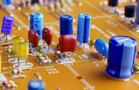
There are several common types of capacitors, each with unique characteristics and potential failure modes.
Ceramic capacitors are small, inexpensive, and widely used in high-frequency applications. They can fail due to mechanical stress, resulting in cracks in the ceramic material, which may cause short circuits or open circuits.

Electrolytic capacitors, including aluminum and tantalum types, have high capacitance values but are polarized. Aluminum electrolytic capacitors often fail due to electrolyte drying out over time, leading to reduced capacitance and increased ESR. Tantalum capacitors are prone to short circuits if subjected to voltage spikes or reverse voltage.

Film capacitors, made of plastic films, are known for their stability and low loss. They can fail due to dielectric breakdown caused by overvoltage, resulting in short circuits.

Supercapacitors, with very high capacitance, may experience capacitance degradation over repeated charge-discharge cycles.

4.1 To test capacitance and understand capacitor behavior in circuits, several tools and methods are available.
Digital Multimeter (DMM) is a versatile tool that can measure capacitance directly. In capacitance mode, it sends a small AC signal to the capacitor and calculates the capacitance based on the response. However, in-circuit measurements may be affected by other components in parallel, so desoldering one terminal can provide more accurate results.
Capacitance meters are dedicated devices that offer higher precision than DMMs for capacitance measurements.
ESR meters are used to measure the equivalent series resistance, which is important for evaluating the performance of electrolytic capacitors. A high ESR indicates a degraded capacitor.
Oscilloscopes can be used to observe the behavior of capacitors in circuits, such as their charging and discharging curves. By analyzing the waveform, one can determine if the capacitor is functioning as expected.
4.2 In-circuit testing methods include:
Visual inspection to check for physical damage like bulging, leakage, or burns.
Voltage measurement to ensure the capacitor is operating within its rated voltage.
Resistance testing to detect short circuits or open circuits. A healthy capacitor will show a low resistance initially as it charges, then rise to a high resistance.
Capacitance testing using a DMM or capacitance meter to compare the measured value with the rated capacitance. A deviation of more than 20% from the rated value indicates a problem.
When working with capacitors and circuits, safety is paramount. Always disconnect the circuit from the power source before testing capacitors. Large capacitors can store a significant amount of charge, so discharge them using a resistor (typically 10kΩ to 100kΩ) to avoid electric shock. Use insulated tools and wear appropriate personal protective equipment, such as gloves and safety glasses, when dealing with high-voltage circuits.
5.1Troubleshooting common issues:
1.If the measured capacitance is significantly lower than the rated value, the capacitor may be degraded or faulty.
2.A shorted capacitor will show zero or very low resistance in a resistance test.
3.An open capacitor will show infinite resistance and no capacitance reading.
4.In cases where in-circuit measurements are inconsistent, check for parallel components that may be affecting the results. Desoldering the capacitor for standalone testing can resolve this issue.
Industry Information








