
Home > Industry Information > Bridge Rectifier Vs Full-Wave Rectifier: A Comprehensive Comparison
In power supply circuits, a rectifier converts alternating current (AC) into pulsating direct current (DC). Bridge rectifiers and full-wave rectifiers are two of the most common rectification schemes. Both utilize both the positive and negative half-cycles of the AC input to achieve full-wave rectification, resulting in higher efficiency and smoother output compared to half-wave rectifiers. Although their ultimate goal is the same, they differ significantly in circuit structure, component count, transformer utilization, cost, and application scenarios. Understanding these differences is essential for power supply design beginners and practicing engineers alike.
A full-wave rectifier uses a center-tapped transformer in combination with two diodes to achieve full-wave rectification.
·A transformer with a center tap on the secondary winding.
·Two rectifier diodes.
·A load resistor.
The secondary winding has a center tap that divides it into two equal halves. The anodes of the two diodes are connected to the two outer ends of the secondary winding, with their cathodes tied together as the positive output terminal. The center tap serves as the negative output terminal (or ground).
·Positive Half-Cycle: During the positive half-cycle of the AC input, the upper half of the secondary winding has a positive polarity at its top and negative at the center tap. The diode connected to the upper half becomes forward-biased and conducts. Current flows from the upper winding end, through the diode, through the load, and returns to the center tap.
·Negative Half-Cycle: During the negative half-cycle, the polarity on the lower half of the secondary winding becomes positive at its bottom and negative at the center tap. The diode connected to the lower half becomes forward-biased and conducts. Current flows from the lower winding end, through its diode, through the load (in the same direction as before), and returns to the center tap.
Key Point: In each half-cycle, only half of the secondary winding is utilized, resulting in lower transformer utilization. However, the output waveform is positive for both half-cycles, achieving full-wave rectification.

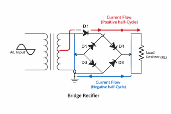
A bridge rectifier uses four diodes arranged in a bridge configuration to achieve full-wave rectification, with the key advantage of not requiring a center-tapped transformer.
·A standard transformer (no center tap).
·Four rectifier diodes connected in a bridge configuration.
·A load resistor.
The four diodes form a bridge: two diodes in one branch, two in the other, with the AC input applied across one diagonal and the load connected across the other diagonal.
·Positive Half-Cycle: When the AC input is positive at the top and negative at the bottom, current flows from the positive input terminal, through diode D1 (forward-biased), through the load (from top to bottom), through diode D2 (forward-biased), and back to the negative input terminal. Diodes D3 and D4 are reverse-biased during this half-cycle.
·Negative Half-Cycle: When the AC input polarity reverses (negative at top, positive at bottom), current flows from the bottom input terminal (now positive), through diode D3 (forward-biased), through the load (still from top to bottom), through diode D4 (forward-biased), and back to the top input terminal (now negative). Diodes D1 and D2 are reverse-biased during this half-cycle.
Key Point: In each half-cycle, two diodes conduct in series. The entire secondary winding is utilized throughout both half-cycles, resulting in high transformer utilization, but the total diode voltage drop (approximately 1.4V) is higher than that of the full-wave rectifier (approximately 0.7V).
IV.Core Comparison
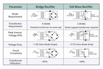
Feature | Full-Wave Rectifier | Bridge Rectifier |
Transformer Requirement | Requires center-tapped transformer | Uses standard transformer |
Number of Diodes | 2 | 4 |
Output Waveform | Full-wave pulsating DC | Full-wave pulsating DC |
Peak Inverse Voltage (PIV) | 2 × Peak Voltage (2Vp) | Peak Voltage (Vp) |
Average Output Voltage | 0.636 × Peak Voltage (2Vp/π) | 0.636 × Peak Voltage (2Vp/π) |
Diode Conduction Loss | 1 diode drop (≈0.7V) | 2 series diode drops (≈1.4V) |
Transformer Utilization | Lower (only half winding used per half-cycle) | Higher (full winding used) |
Cost Structure | Higher transformer cost, fewer diodes | Lower transformer cost, more diodes |
Typical Applications | Low voltage, high current (sensitive to voltage drop) | High voltage, small to medium current (cost-sensitive) |
This is a critical parameter for diode selection.
·Full-Wave Rectifier: When one diode is conducting, the other diode must withstand the full secondary voltage (from one outer end to the other), which is 2 × Vp (where Vp is the peak voltage from the center tap to one winding end). Thus, PIV = 2Vp.
·Bridge Rectifier: During either half-cycle, one reverse-biased diode withstands only the peak input voltage from the transformer secondary, which is Vp. Thus, PIV = Vp.
This means that for the same output voltage requirement, the bridge rectifier can use diodes with a lower voltage rating.
·Full-Wave Rectifier: Only half of the secondary winding is active during each half-cycle. This results in lower copper utilization, requiring a larger transformer for the same power output.
·Bridge Rectifier: The entire secondary winding is active throughout both half-cycles. This means the transformer is used more efficiently, allowing for a smaller and more economical transformer for the same power rating.
·Full-Wave Rectifier: Current flows through only one diode during each half-cycle, with a voltage drop of approximately 0.7V. This is advantageous in high-current, low-voltage applications.
·Bridge Rectifier: Current flows through two diodes in series during each half-cycle, with a total voltage drop of approximately 1.4V. In low-voltage, high-current circuits, this additional loss can significantly reduce efficiency.
·Low-Voltage, High-Current Applications: Such as electroplating power supplies or battery chargers where diode voltage drop is a critical factor.
·When a Center-Tapped Transformer is Already Available: In repairs or retrofitting existing equipment, this structure can be retained.
·High-Reliability Applications Sensitive to Component Count: Two fewer diodes means fewer potential failure points.
·High-Voltage Applications: Such as high-voltage power supplies or primary rectification in switch-mode power supplies, where the diode drop is a small percentage of the total voltage and transformer cost is a major factor.
·Cost-Sensitive Mass Production: Standard transformers are more readily available and less expensive than center-tapped transformers.
·When Using Integrated Bridge Rectifier Modules: Four diodes can be packaged into a compact, easy-to-mount bridge rectifier module, simplifying assembly and heat sinking.
Both the bridge rectifier and the full-wave rectifier are effective solutions for converting AC to pulsating DC, each with its own set of advantages and disadvantages. The full-wave rectifier offers advantages in component count and conduction loss but requires a specialized and less efficiently utilized center-tapped transformer, making it better suited for low-voltage, high-current applications. The bridge rectifier, on the other hand, provides benefits such as the ability to use a standard transformer, lower diode voltage stress, and higher transformer utilization. While it uses two additional diodes, the overall cost structure—especially in mass production—often favors the bridge rectifier, which has become the dominant choice in modern power supplies. Understanding the working principles and trade-offs between these two rectifier types enables beginners and engineers to make more informed decisions in circuit design.
Industry Information








