
Home > Industry Information > Sample-And-Hold Amplifiers: Capturing Instantaneous Analog Signals
This article provides a concise introduction to Sample-and-Hold Amplifiers (S/H), key circuits that capture and hold an instantaneous analog voltage for later processing. It explains their two operational phases—Sample and Hold—and their core switched-capacitor architecture. Key performance parameters and primary application areas, such as data acquisition and ADC front-ends, are also outlined.
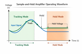
A Sample-and-Hold Amplifier is a mixed-signal circuit that acquires the instantaneous voltage of an input analog signal at a precise moment (controlled by an external logic signal) and maintains this voltage value unchanged at its output for a subsequent period.
Its basic function can be broken down into two well-defined phases:
Sample (or Track) Phase: During this phase, an internal switch is closed, and the circuit's output follows changes in the input signal at high speed, much like a voltage follower.
Hold Phase: Upon receiving a "Hold" command, the switch opens precisely at that instant. The circuit "memorizes" the voltage present at the input at the moment of disconnection on a high-quality hold capacitor and outputs this constant voltage throughout the hold period.
More broadly, when the circuit exhibits excellent dynamic tracking performance during the sample phase, it is often called a Track-and-Hold Amplifier. An ideal S/H amplifier's output should perfectly match the input during sampling and be a perfectly horizontal line during hold.
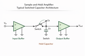
The most classic S/H amplifier circuit employs a switched-capacitor architecture. Its core consists of three main parts:
Core Section | Components | Function & Requirements |
Input Buffer Amplifier (A1) | High-speed, high-input-impedance op-amp | Presents a high-impedance load to the signal source to prevent loading effects and rapidly charges/discharges the hold capacitor. |
Analog Switch (S) | MOSFET (commonly used) or JFET | Opens and closes rapidly and cleanly under logic control. Its switching transients are a primary source of error. |
Hold Capacitor (C_H) | High-quality polystyrene, polypropylene, or Teflon capacitor | The core memory element of the entire circuit, storing the sampled voltage. Its dielectric absorption, leakage current, and value are critical. |
Output Buffer Amplifier (A2) | High-input-impedance, low-bias-current op-amp | Isolates the capacitor, provides a low-impedance output, and prevents the held voltage from drooping due to load discharge. |
Detailed Work Process:
Sample Mode: Switch S is closed. A1 acts as a voltage follower, rapidly charging/discharging C_H so that its voltage equals the current input voltage V_IN. At this time, V_OUT = V_IN.
Hold Command Issued: The logic control circuit issues a "Hold" command. This is the most critical instant, requiring switch S to open completely within an extremely short time (Aperture Time). The precise moment the switch opens determines the held voltage value.
Hold Mode: Switch S is open. Ideally, the voltage on C_H is perfectly "frozen." A2, utilizing its very high input impedance, continuously reads and outputs the voltage on C_H. In practice, due to A2's input bias current and the capacitor's own leakage, the voltage on C_H slowly decays, a phenomenon known as Droop Rate or Voltage Droop.
Understanding and weighing the following parameters is key to selecting the right S/H amplifier:
Parameter | Definition & Impact |
Acquisition Time | Time from the sample command to when the output tracks an input step change within a specified accuracy (e.g., 0.01%). Determines the maximum sampling frequency. |
Aperture Time | Fixed delay between the "Hold" command and the actual complete opening of the analog switch. It introduces a fixed offset on the time axis. |
Aperture Jitter | Random variation in the aperture time. This is one of the most critical parameters limiting the performance of high-speed, high-dynamic-range ADCs, as it directly translates to voltage uncertainty at the sampling instant. |
Droop Rate / Hold Mode Settling | Rate at which the output voltage decays over time in hold mode (typically in mV/µs or µV/µs). Primarily determined by hold capacitor leakage and output buffer input bias current. |
Setting Time | Time required for the output to settle to its final stable value (within a given error band) after entering hold mode. Affected by disturbances from switch charge injection. |
Nonlinearity Error | Maximum deviation of the device's transfer function from an ideal straight line across the full input voltage range. |
Feedthrough | During hold mode, changes in the input signal can still couple to the output via the switch's parasitic capacitance, appearing as unwanted AC components. |
S/H amplifiers primarily serve systems requiring high-performance, synchronous data conversion:
Multi-Channel Synchronous Data Acquisition Systems: This is the classic application. Multiple channels of analog signals need to be sampled at the same instant. Using one S/H per channel, all controlled by the same "Hold" signal, achieves an "instantaneous snapshot" of all channels. The ADC then digitizes the held voltages channel by channel.
Front-End for High-Speed, High-Resolution ADCs: Almost all high-performance successive-approximation-register (SAR) and pipeline ADCs with resolutions above 16 bits and sampling rates exceeding a few MSPS integrate an S/H circuit internally or require an external S/H to ensure sampling accuracy.
Pulse and Transient Signal Analysis: Used to capture the peak value of single-shot or low-repetition fast pulses.
Digital Oscilloscopes: Used in equivalent-time sampling mode to accurately capture different phase points of a repetitive waveform.
Automatic Test Equipment and Precision Instruments: Ensures measurements of the device under test occur at a deterministic point in time.

With advances in semiconductor processes, modern S/H amplifiers are evolving toward higher speed, lower power consumption, and higher integration. Many high-performance ADCs now integrate optimized S/H circuits as their front-end core.
Key Selection Considerations:
·Speed vs. Accuracy: Determine the S/H's acquisition time, aperture jitter, and settling time based on the system's required sampling rate and target resolution (number of bits).
·System Architecture: Is it for multi-channel synchronous sampling or as a front-end for a single high-speed ADC? This dictates whether discrete S/H chips or an ADC with integrated S/H is needed.
·Error Budget Allocation: Incorporate errors like aperture jitter, nonlinearity, and droop rate into the overall data acquisition chain's error budget, ensuring the S/H's contribution doesn't compromise total system performance.
·Parameter Priority: For high-frequency signals, aperture jitter is paramount. For high-precision DC or low-frequency measurements, droop rate, nonlinearity, and settling accuracy are more critical.
The Sample-and-Hold Amplifier is an ingenious invention in the field of analog signal processing. Through the simple yet powerful "switch-capacitor" structure, it elegantly solves the core challenge of discretizing continuous-time signals. From simple discrete circuits to complex modules integrated into cutting-edge ADCs, its design consistently focuses on achieving the optimal balance between speed, accuracy, and dynamic performance. Understanding its working principles, key non-ideal characteristics, and their impact on system performance is foundational for designing high-performance data acquisition systems and digital signal processing front-ends. In the wave of digital transformation, this "shutter" that captures instantaneous reality from the analog world will continue to play an irreplaceable role in bridging the physical and digital realms.
Industry Information








