
Home > Industry Information > Bridge Rectifier: A Detailed Guide To Working Principles, Circuits, And Applications
This passage is a comprehensive guide to the Bridge Rectifier, a fundamental circuit for AC-to-DC conversion. It explains how its four-diode full-wave design efficiently converts both halves of the AC input into a unidirectional DC output. Key advantages like high efficiency and not needing a center-tapped transformer are highlighted. The article details its waveform, the need for filtering, and its wide application as the essential first stage in power supplies, battery chargers, motor drives, and consumer electronics. Practical selection and usage tips conclude the guide.
A bridge rectifier, also known as a diode bridge, is a type of full-wave rectifier typically composed of four diodes arranged in a bridge configuration. When an AC voltage is applied to the input terminals, the rectifier ensures that both the positive and negative half-cycles of the AC waveform are converted into a unidirectional (same-polarity) output current.
Compared with a half-wave rectifier—which utilizes only one half of the AC cycle—the bridge rectifier makes use of both half-cycles, resulting in higher efficiency and improved output performance.

The core of a bridge rectifier consists of four diodes (commonly labeled D1, D2, D3, and D4) connected in a closed-loop bridge arrangement. The AC input is applied to one pair of opposite nodes, while the DC output (connected to the load) is taken from the other pair.
Operating Principle
·Positive Half-Cycle:During the positive half-cycle of the AC input, diodes D1 and D2 are forward-biased and conduct current, while D3 and D4 are reverse-biased. Current flows through D1 → load → D2, producing a positive output across the load.
·Negative Half-Cycle:When the input polarity reverses during the negative half-cycle, diodes D3 and D4 conduct while D1 and D2 block current. The current path becomes D3 → load → D4. Despite the reversed input polarity, the current through the load remains in the same direction.
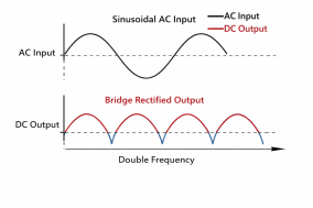
Through this alternating conduction, the bridge rectifier achieves full-wave rectification, ensuring a continuous unidirectional current at the output.

The bridge rectifier's status as an industry standard stems from its multiple advantages:
Feature | Description & Advantage |
Full-Wave Rectification | Utilizes the entire AC cycle. Efficiency is nearly double that of half-wave rectifiers. Output ripple frequency is twice the input frequency, making it easier to filter. |
High Efficiency | Low diode voltage drop (typically ~0.7V per silicon diode), resulting in relatively low conduction losses. |
No Center-Tapped Transformer Required | A significant advantage over other full-wave rectifier circuits (using a center-tapped transformer), reducing transformer cost and complexity. |
Compact Structure | The four diodes can be integrated into a single package, forming a bridge rectifier stack or module, which is small in size and easy to install. |
High Reliability | Simple circuit, mature components, long lifespan. |
Output Waveform: The unfiltered output is a pulsating DC. Its peak voltage Vp(out)Vp(out) is approximately equal to the peak AC input voltage Vp(in)Vp(in) minus the forward voltage drop of two diodes (about 1.4V).
·Formula: Vp(out)≈Vp(in)−1.4VVp(out)≈Vp(in)−1.4V
Average Output Voltage: For an ideal sine wave, the average DC voltage after full-wave rectification is about 0.9 times the RMS value of the AC input.
Filtering: In practical applications, a large-value electrolytic capacitor must be connected in parallel at the output for filtering. The capacitor charges during voltage peaks and discharges to the load during troughs, smoothing the waveform into DC voltage with lower ripple. Larger capacitance and lighter loads result in smaller ripple.
The bridge rectifier is the first "gateway" in almost all devices that need to convert mains electricity (AC 220V/110V) to DC:
Linear Regulated Power Supplies: Serves as the front-end AC/DC conversion stage, providing unregulated DC input to subsequent linear regulator chips (e.g., 78xx series).
Switch-Mode Power Supplies (SMPS): At the input stage of an SMPS, it rectifies mains AC to high-voltage DC, which is then efficiently converted by a high-frequency switching circuit.
Battery Chargers: Provides the primary DC power source for charging lead-acid, lithium-ion batteries, etc.
Motor Drives and Control Systems: Powers DC motors or control circuit boards.
Welding Equipment: Provides stable DC welding current in some arc welders.
Consumer Electronics: From household appliances to computers and TVs, the internal power boards of all these devices rely on bridge rectifiers.

Diode Parameters: When selecting diodes, the Peak Inverse Voltage (PIV) and Average Forward Current ratings must have sufficient margin to handle input surges and load variations.
Heat Dissipation: In high-current applications, the rectifier bridge generates significant heat and often requires a heatsink.
Inrush Current: The initial charging of the filter capacitor at power-on creates a large inrush current, which can damage the diodes. An NTC thermistor is usually connected in series to suppress this.
Electromagnetic Interference (EMI): The rectification process is non-linear and can generate high-frequency noise. Filtering components on the input side are often necessary to meet electromagnetic compatibility requirements.
With its simple, efficient, and reliable characteristics, the bridge rectifier serves as a cornerstone of modern power technology. Understanding the "current-directing bridge" formed by four diodes and mastering the principles of full-wave rectification and filter design is a crucial step into the field of power electronics. Whether as discrete components or integrated modules, it plays an indispensable role in "taming" AC into usable DC. As semiconductor technology advances, its performance and reliability continue to improve, serving a wide range of applications from microelectronic devices to large-scale industrial systems.
Industry Information








