
Home > Industry Information > Multimeter:Everything You Should To Know
This passage serves as a comprehensive guide to multimeters, covering their fundamental concepts, operational mechanisms, and practical applications. It specifically elaborates on measuring microfarads with multimeters, provides step-by-step usage instructions, and concludes with key takeaways, aiming to help readers fully understand and proficiently use this essential electronic testing tool.
2.1 what is a multimeter
A multimeter, also known as a volt-ohm-milliammeter (VOM), is a versatile electronic measuring instrument that integrates multiple measurement functions in one device. It can typically measure direct current (DC) and alternating current (AC) voltage, direct current (DC) and alternating current (AC) current, resistance, and in many cases, additional parameters such as capacitance, frequency, temperature, and diode/transistor characteristics. Available in both analog (pointer-type) and digital (LCD/LED display) versions, multimeters are indispensable tools for electricians, electronic engineers, hobbyists, and maintenance technicians.
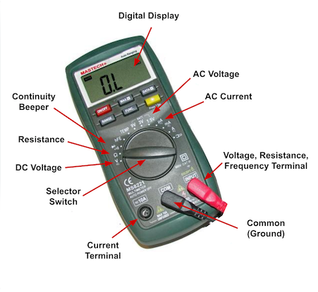
2.2 working principle
The core working principle of a multimeter lies in converting various physical quantities (voltage, current, resistance, etc.) into measurable electrical signals and processing them to display the results. For voltage measurement, it uses a high-resistance voltage divider circuit to reduce the measured voltage to a range suitable for the internal meter movement or analog-to-digital converter (ADC). When measuring current, a low-resistance shunt resistor is employed to convert current into a proportional voltage. Resistance measurement relies on an internal voltage source that supplies a current to the measured resistor, with the voltage drop across the resistor measured and converted to resistance value using Ohm’s Law (R = V/I). Advanced multimeters add dedicated circuits for capacitance, frequency, and other measurements—for example, capacitance measurement often uses an oscillator whose frequency changes with capacitance, and the frequency is then converted to a capacitance reading.
2.3 typical applications
Household Maintenance:Check if AC power outlets output normal voltage (e.g., 120V/230V) to diagnose faulty sockets; test the remaining charge of batteries (AA, AAA, lithium-ion, etc.) by measuring DC voltage; detect open/short circuits in household wiring (e.g., lamp cords, appliance power lines) via resistance measurement.
Electronics Repair:Troubleshoot circuit boards by measuring voltage at key nodes to identify abnormal signal paths; verify the actual value of discrete components (resistors, capacitors, diodes) against rated parameters; check for open circuits (infinite resistance) or short circuits (near-zero resistance) in solder joints and component leads.
Industrial Settings:Conduct routine maintenance of electrical equipment (e.g., motors, transformers) by measuring winding resistance to detect insulation degradation; verify the output voltage/current of industrial power supplies to ensure stable operation of production lines; test the continuity of safety circuits (e.g., emergency stop loops) to meet industrial safety standards.
Hobbyist&Educational Use:Experiment with basic circuits (e.g.,series/parallel resistor networks) by measuring voltage drops and current flows to validate Ohm’s Law; test assembled electronic kits (e.g.,radio receivers, Arduino projects) to ensure components work as designed; teach students core electronics concepts through hands-on measurement of electrical quantities.
Automotive Maintenance:Check the voltage of car batteries (typically 12V DC) to assess charging status; measure the resistance of ignition coils and sensors (e.g., oxygen sensors) to diagnose engine performance issues; test the continuity of automotive wiring harnesses to find broken connections.
3.1AC/DC Voltage Range
Symbol: "V~" (with a wavy line under "V") for AC voltage; "V—" (with a straight line under "V") for DC voltage.
Function: "V~" is used to measure alternating current voltage, such as the voltage of mains power or generators. "V—" is for measuring direct current voltage, like the voltage of batteries or DC power supplies on circuit boards.
3.2AC/DC Current Range
Symbol: "A~" (with a wavy line under "A") for AC current; "A—" (with a straight line under "A") for DC current.
Function: Used to measure the current intensity in a circuit. For example, it can detect the power consumption of electrical appliances or the current in a component loop.
3.3Resistance Range
Symbol: "Ω" (Ohm).
Function: Measures the resistance value of conductors. It can be used to check whether components (such as resistors) are damaged or to test the on-off status of wires.
3.4Diode/Continuity Test Range
Symbol: Diode icon (similar to a triangle with a vertical line at one end).
Function: Serves two purposes: measuring the forward voltage drop of diodes and testing circuit continuity. When testing continuity, the multimeter’s buzzer sounds if the circuit is conducting.
3.5Capacitance Range
Symbol: Capacitor icon or capacitance units such as "μF" (microfarad) and "nF" (nanofarad).
Function: Measures the capacitance of capacitors, helping to check if capacitors are faulty or if their capacitance deviates from the rated value.
3.6Transistor Test Range
Symbol: Transistor icon (NPN or PNP type).
Function:Tests parameters of transistors, such as the current amplification factor (hFE), to judge the performance of transistors.
3.7Temperature Measurement Range
Symbol:Thermometer icon or temperature units such as "℃" (Celsius) and "℉" (Fahrenheit).
Function:Used to measure temperature (e.g., ambient temperature or component surface temperature) when paired with a temperature probe.

Safety Preparation:Wear appropriate personal protective equipment (PPE) such as insulated gloves when working with high-voltage circuits. Inspect the multimeter’s test leads for damage (e.g.,cracked insulation) and replace them if faulty.Ensure the multimeter is calibrated(per manufacturer recommendations) for accurate measurements.
Function & Range Selection:Identify the quantity to be measured (voltage, current, resistance, etc.) and select the corresponding function on the multimeter. Choose a range that is higher than the expected value—for example, select the 20V AC range to measure household outlet voltage (typically 120V or 230V; adjust range accordingly). For auto-ranging multimeters, the device will automatically select the appropriate range.
Voltage Measurement:For DC voltage, connect the red test lead to the “VΩmA” port and the black lead to the “COM” (common) port. Touch the red lead to the positive terminal and the black lead to the negative terminal of the circuit/component. For AC voltage, the lead polarity does not matter. Read the displayed voltage value.
Current Measurement:Set the multimeter to the current function (DC or AC). For low current (e.g., mA), connect the red lead to the “mA” port; for high current (e.g., A), use the “A” port. Break the circuit and insert the multimeter in series with the load—connect the red lead to the positive side of the break and the black lead to the negative side. Read the displayed current value (avoid measuring current in parallel, as this may damage the multimeter).
Resistance Measurement:Turn off the circuit power (resistance measurement requires no external power).Connect the test leads to the resistor terminals (polarity does not matter). The multimeter will display the resistance value. For “OL” readings, the resistor is open; for near-zero readings, the resistor is shorted.
Post-Measurement Steps:Turn off the multimeter or set it to the highest voltage range (to protect it from accidental voltage exposure).Disconnect the test leads and store the multimeter in a dry, clean place.

In conclusion, a multimeter is a versatile and essential tool for measuring various electrical quantities. Understanding its definition, working principle, and typical applications lays the foundation for proper use. Mastering capacitance measurement (especially in microfarads) and following standardized usage steps—from safety preparation to function selection and post-measurement care—ensures accurate, safe, and efficient testing. Whether for professional work or hobbyist projects, proficiency with a multimeter is key to successful electrical and electronic work.
Industry Information








